I have been playing with 2FSK demodulation using a RTL-SDR and GNURadio Companion.
To start with, I used an OpenLST radio board as my RF Transmitter. OpenLST is an open source radio module by Planet. OpenLST comes with an UART interface where we can command it to transmit packets of data. My OpenLST was configured as followes.
Center Frequency: 449.9MHz
Data Rate: 7416 baud
Modulation Scheme : 2FSK
FSK Frequency Deviation: 3707Hz
Sync word: 0XAB35
First, I observed the OpenLST output using the RTL-SDR and Console.
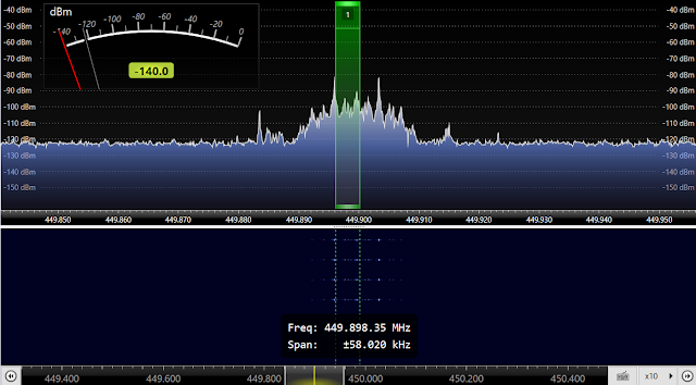
According to the above screen capture, the transmit signal is centered around 449.9MHz. In 2-FSK, two frequencies are used to transmit logic 0 and logic 1. The absolute value of the difference between the center frequency and the mark or space frequency is known as the frequency deviation, and the OpenLST is configured with 3707 Hz frequency deviation. In the above figure, we can see the peaks at mark and space frequencies.
In order to demodulate the OpenLST signal, I am using GNURadio Companion and a Windows 10 PC. Following figure shows my GNURadio schematic.
First, I capture the output of OpenLST using RTL-SDR. The center frequency was set to 449.9MHz and the selected channel bandwidth is 10kHz. Then, I used a Power Squelch. This will get rid of noisy demodulated signals when the incoming power level is less than -5dB. After that I used a low pass filter with a cut-off frequency of 20kHz to filter out noise components. The demodulation block I used here is Quadrature Demod block. OpenLST is transmitting at a buad rate of 7416. Since I am using 2 x 10^6 samples per second, there are (2 Mega)/7416 samples per symbol. Hence there are 269 samples per symbol. Here I used a moving average filter of size 269 to filter out the demodulated signal. Then there is a Binary slicer which converts the demodulated signal into a bit stream.
The output from the low pass filter and the demodulated signal is shown in the following figure.
The top graph shows the filtered IQ components and as you can see, there are two packets were transmitted from OpenLST. In the decoded signal, we can see that the sync word was transmitted twice. Before the sync words there are the preamble bits which helps with synchronization.
To start with, I used an OpenLST radio board as my RF Transmitter. OpenLST is an open source radio module by Planet. OpenLST comes with an UART interface where we can command it to transmit packets of data. My OpenLST was configured as followes.
Center Frequency: 449.9MHz
Data Rate: 7416 baud
Modulation Scheme : 2FSK
FSK Frequency Deviation: 3707Hz
Sync word: 0XAB35
First, I observed the OpenLST output using the RTL-SDR and Console.
According to the above screen capture, the transmit signal is centered around 449.9MHz. In 2-FSK, two frequencies are used to transmit logic 0 and logic 1. The absolute value of the difference between the center frequency and the mark or space frequency is known as the frequency deviation, and the OpenLST is configured with 3707 Hz frequency deviation. In the above figure, we can see the peaks at mark and space frequencies.
In order to demodulate the OpenLST signal, I am using GNURadio Companion and a Windows 10 PC. Following figure shows my GNURadio schematic.
The output from the low pass filter and the demodulated signal is shown in the following figure.
The top graph shows the filtered IQ components and as you can see, there are two packets were transmitted from OpenLST. In the decoded signal, we can see that the sync word was transmitted twice. Before the sync words there are the preamble bits which helps with synchronization.
Subscribe by Email
Follow Updates Articles from This Blog via Email


No Comments