Thursday, April 16, 2020

thumbnail

Getting Started with STM32FDIS-BB, Camera, and LCD with System Workbench

I started playing with STM34FDIS-BB expansion board with the LCD and Camera module. The expansion board supports STM32F407-Discovery board. When the discovery board is combined with all the expansion boards, you get a handy setup where you can capture images using an Ominivision OV9655 sensor and display it on a TFT LCD. 

All the schematic designs for the expansion boards are available here, and software examples are available here. These documents and example codes are useful to gain a better insight into the expansion boards. However, the issue I faced was all the software examples support either IAR Embedded Workbench or MDK Arm Keil IDE, and those IDEs are not free to use. As I use System Workbench IDE, I created a System Workbench project with the LCD plus Camera software example. The project is available here. Hopefully it would be helpful to someone when they want to use STM34FDIS-BB expansion board with System Workbench.


Monday, April 6, 2020

thumbnail

Closer Look at 2FSK Demodulated Message

I tried demodulating a signal transmitted from an OpenLST transceiver using a RTL-SDR dongle here. Now I am going to take a closer look at the demodulated signal.
Structure of the transmit packet from OpenLST is as follows. In the test transmission I did here, I transmitted a single byte of data, 0XFF. OpenLST uses a TI C1110 chip and, C1110 adds many other bytes to the transmit packet for synchronization and error checking. My OpenLST transmitter is configured with the following packet structure.

Byte 0: Preamble (0xAA)
Byte 1: Preamble (0xAA)
Byte 2: Preamble (0xAA)
Byte 3: Preamble (0xAA)
Byte 4: Sync word (0xAB)
Byte 5: Sync word (0x35)
Byte 6: Sync word (0xAB)
Byte 7: Sync word (0x35)
Byte 8: Length of the packet except preamble and sync word (in my case 0x08)
Byte 9: Flag Byte (0x40)
Byte 10: Sequence number
Byte 11: Sequence number
Byte 12: Radio in (0x01)
Byte 13: Command (In my case command for tx data is 0x1C)
Byte 14: Transmit Data (In the specific case I consider here, its only one byte, 0xFF)
Byte 15: Hardware ID (in my case 0xCA)
Byte 16: Hardware ID (in my case 0xCA)

Tx packet starts with a preamble. This is a string of bits which helps the receiver to identify the receive data baud rate. After the preamble, the sync word repeats twice. Sync word helps to identify the byte boundaries and functions as a system identifier as sync word can be set unique to a transmitter,

CC1110 uses a process called 'whitening' to achieve better power distribution over the allocated bandwidth. Whitening is used to avoid long strings of logic ones or zeros. All the bits in the Tx packet except preamble and sync word are XOR-ed with a 9 bit pseudo random number. Pseudo random number generation process in C1110 is described in TI Design Note DN509. The generator starts with assigning all bits to 1. (1 1111 1111). 8 least significant bits of this is used as the first whitening key. To generate the MSB of the next pseudo random number, bit 5 and bit 0 are XORed and bits are shifted to right by 1. Following figure demonstrates this process and the image is obtained from TI Design Note DN509.


The 8 least significant bits from every 8th pseudo random number generated are used as whitening keys. We can list the whitening keys as follows.

WK1: 0xFF
WK2: 0xE1
WK3: 0x1D
WK4: 0x9A
WK5: 0xED
WK6: 0x85
WK7: 0x33
WK8: 0x24
WK9: 0xEA
WK10: 0x7A

Then the transmit bytes of the packet we considered earlier can be obtained as follows.

TX Byte 0 0xAA No whitening
TX Byte 1 0xAA No whitening
TX Byte 2 0xAA No whitening
TX Byte 3 0xAA No whitening
TX Byte 4 0xAB No whitening
TX Byte 5 0x35 No whitening
TX Byte 6 0xAB No whitening
TX Byte 7 0x35 No whitening
TX Byte 8 0xF7 0x08 XOR 0xFF (Byte 0 XOR WK1)
TX Byte 9 0xA1 0x40 XOR 0xE1 (Byte 1 XOR WK2)
TX Byte 10 0x1D 0x00 XOR 0x1D (Byte 2 XOR WK3)
TX Byte 11 0x9B 0x01 XOR 0x9A (Byte 3 XOR WK4)
TX Byte 12 0xEC 0x01 XOR 0xED (Byte 4 XOR WK5)
TX Byte 13 0x99 0x1C XOR 0x85 (Byte 5 XOR WK6)
TX Byte 14 0xCC 0xFF XOR 0x33 (Byte 6 XOR WK7)
TX Byte 15 0xEE 0xCA XOR 0x24 (Byte 7 XOR WK8)
TX Byte 16 0x20 0xCA XOR 0xEA (Byte 8 XOR WK9)

By taking a closer look at the decoded bit stream, I identified the transmitted packet byte values as in the following figure.


We can see that the decoded data are the same as whitened tx data we calculated above using the whitening keys. 

Thursday, April 2, 2020

thumbnail

Convert RTL-SDR Dipole into a Yagi Antenna for NOAA

A few months ago I bought my RTL-SDR from Amazon, and I bought the dipole antenna coming with the SDR dongle too. My initial objective was to get some NOAA images decoded using the dipole and the SDR. There are plenty of tutorials on how to set up the required software such as SDR Sharp, Virtual Audio output, and WXtoIMG for NOAA reception and decoding.

I used my dipole antenna as V-dipole as in here for my initial setup. In addition, an LNA with an FM bandstop filter is used to suppress strong FM transmission.

This is one of the images I managed to decode.


As you can see, I got a good reception when the satellite was more or less passing through overhead, but the signal quality deteriorates when the satellite was closer to the horizon. In my home, I only have access to the West horizon. Because of that, I think a directional antenna would work better for my situation. However, I don't want to have an antenna with too narrow beamwidth because if the beamwidth is too narrow, I will need to have an antenna rotator to get horizon to horizon reception. 

To improve the performance of the system, I wanted to make a Yagi antenna for 137 MHz range. I decided to start with a 3 element Yagi antenna because of several reasons. Yagi antenna usually consists of a reflector, an active element, and one or more directors. The beamwidth of the antenna narrows down with the increased number of directors. In my case I don't have an antenna rotator, because of that I didn't want to make my antenna beamwidth too narrow. With a single director, I managed to design a Yagi with about 60 degrees beamwidth, which is perfect for my situation.
In the design stage of the antenna, I used this online calculator with YagiCAD.

These are the dimensions of my design.

Reflector length: 1.0839 m
Active element length: 1.0358 m
Director length: 0.9635 m
Reflector to dipole spacing: 0.2737 m
Dipole to director spacing:  0.2737 m

With these parameters, I obtained the following radiation pattern using YagiCad.


I used RTL-SDR dipole as the active element for the Yagi. I made the reflector and the director with a piece of metal tape measure. This figure shows my dodgy Yagi antenna made out of tape measure, dipole and piece of wood. 


Time to listen to a NOAA satellite using my new Yagi antenna. I mounted the antenna such that the antenna axis is 45 degrees to the horizontal plane. I managed to get a better reception compared to V-dipole, and this is one of the decoded images.


Wednesday, April 1, 2020

thumbnail

2FSK Demodulation with RTL-SDR and GNURadio

I have been playing with 2FSK demodulation using a RTL-SDR and GNURadio Companion.
To start with, I used an OpenLST radio board as my RF Transmitter. OpenLST is an open source radio module by Planet. OpenLST  comes with an UART interface where we can command it to transmit packets of data. My OpenLST was configured as followes.

Center Frequency: 449.9MHz
Data Rate: 7416 baud
Modulation Scheme : 2FSK
FSK Frequency Deviation: 3707Hz
Sync word: 0XAB35

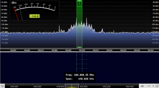
First, I observed the OpenLST output using the RTL-SDR and Console.


According to the above screen capture, the transmit signal is centered around 449.9MHz. In 2-FSK, two frequencies are used to transmit logic 0 and logic 1. The absolute value of the difference between the center frequency and the mark or space frequency is known as the frequency deviation, and the OpenLST is configured with 3707 Hz frequency deviation. In the above figure, we can see the peaks  at mark and space frequencies. 

In order to demodulate the OpenLST signal, I am using GNURadio Companion and a Windows 10 PC. Following figure shows my GNURadio schematic. 


First, I capture the output of OpenLST using RTL-SDR. The center frequency was set to 449.9MHz and the selected channel bandwidth is 10kHz. Then, I used a Power Squelch. This will get rid of noisy demodulated signals when the incoming power level is less than -5dB. After that I used a low pass filter with a cut-off frequency of 20kHz to filter out noise components. The demodulation block I used here is Quadrature Demod block. OpenLST is transmitting at a buad rate of 7416. Since I am using 2 x 10^6 samples per second, there are (2 Mega)/7416 samples per symbol. Hence there are 269 samples per symbol. Here I used a moving average filter of size 269 to filter out the demodulated signal. Then there is a Binary slicer which converts the demodulated signal into a bit stream.

The output from the low pass filter and the demodulated signal is shown in the following figure.


The top graph shows the filtered IQ components and as you can see, there are two packets were transmitted from OpenLST. In the decoded signal, we can see that the sync word was transmitted twice. Before the sync words there are the preamble bits which helps with synchronization.


Search This Blog

Powered by Blogger.